Part 2
The printer project is finished meanwhile. Beside the thermal printer itself, the RFID reader and the buttons it got another feature which I had to build in.
The friend of mine who is using it, would also like to switch an illuminated open-sign in the shopwindow of his gym on and off automatically. As the linux-based point-of-sale system I've developed for him contains kind of a job scheduler already, why not putting a sender into this printer as well, which can control some relais remotely? :-)
(I'm afraid of the day already, this multi feature printer will stop working for whatever reason...)
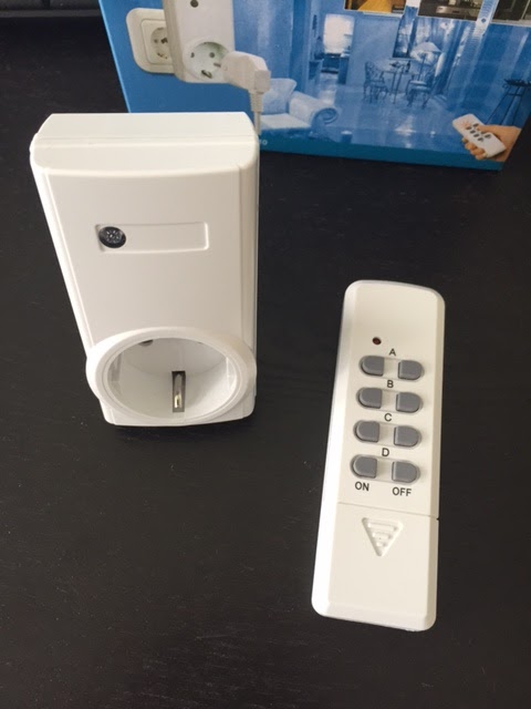
 Considering how much effort it might be to build such a remote controlled switch by myself I quickly decided for connecting one of these remote control sets, which I found for just 12 bucks in the internet. It comes with one remote and 3(!) socket switches. Frankly I'm almost a bit shocked how cheap this stuff can be produced.
Anyway, after opening the remote to find out how to connect it to the microcontroller it turned out that I would need some additional components to get it running with the microcontroller.

Each of these "gum-buttons" on the remote is connecting 3 contacts with each other, which made it a bit more complicated. After measuring through the small board of the remote I decided to do that simply by a couple of relais with 2 changeover switches each. Became more cabling than I wanted, but eventually worked.
Next complication of this remote is its power supply - they deliver it with a 12V battery. :-(
I only have a 5V power supply in the printer and didn't really want to replace the powersupply with something else. So checking power consumption of the remote turned out to be low, in fact very low. :-)

Low enough to use a step-up converter making 12V out of my 5V. I've used a NME0512SC for it, which does everything without any additional capacitor etc. and delivers 12V out of 5V with a maximum of 83mA. Ok, in total the costs of the step-up converter plus the 4 relais to connect the remote with the microcontroller is more expensive than the whole set of remote and switched sockets, but now that I bought it already...
Here are the 4 relais with the step-up converter on the right side on a little extra board:


So, mechanically that's probably the maximum I can put into this box. :-)
They layout how buttons, their LEDs, the 4 relais, the printer and the RFID-reader is connected to the microcontroller looks like this:

The buttons are connected directly. In the firmware we will activate an internal pull-up resistor on the input ports of the microcontroller.
The LEDs are connected directly as well with a 330Ohm resistor, which currentwise is working well. For some reason I've soldered them accidently connected to +5 volts, as I was too lazy to change that later on, I simply inverted the signal in the program. So switching the pin off, when LED should be on and the other way around.
The buttons I've used you can find here: LED Button Adafruit.com I think they are quite cheap for an LED button - and I love their high resolution pictures in the shop. :-)
The relais are connected with a standard transistor layout.
The ATMEGA1284 has two different serial ports, which makes internal programming of the firmware a bit easier. The printer is running at 19200 baud, the RFID reader at 9600.
The layout of the board you can find here: Microcontroller Layout (Pollin.de) on page 7.
I usually buy the whole kit there, (mainly because of the board) and solder only the components I need.
Link to building kit: building kit (Pollin.de)
As microcontroller I've used the ATMEGA1284 instead of the ATMEGA32. This allows me for implementation of a bootloader via ethernet and dhcp support. Which makes firmware updates via tftp server much, much easier during developing.
All firmware files (bootloader and firmware itself) are available here:
Printer Firmware
The bootloader comes with fixed IP and gateway addresses (can be changed of course)
IP 192.168.0.23 and gateway 192.168.0.1 (usually that is the same as router address).
The bootloader expects a tftp server on 192.168.0.40 with the file printerlinkfw.bin
The firmware of the printer can be remote controlled with the following command on linux:
echo "c6 set cmdopt 1" | nc 192.168.x.x 2701 -w 1
This example sets the variable cmdopt to 1 on the microcontroller. It gets send via piping to the nc command followed by the IP address of the device and its port (2701). The option -w 1 allows to see any reply of the microcontroller.
The following values for cmdopt are supported:
1 - switching on LED of green button
2 - switching on LED of red button
3 - switching on LED of white button
4 - switching off LED of green button
5 - switching off LED of red button
6 - switching off LED of white button
8 - switching on remote socket channel 1
9 - switching off remote socket channel 1
10 - switching on remote socket channel 2
11 - switching off remote socket channel 2
If a button gets pressed the printer will send an UDP message like "btn green" to the IP address which is written in the eeprom from address 0-3.
The IP address in eeprom can be programmed with
echo "eew 0 c0a80063" | nc 192.168.x.x 2701 -w 1
for e.g. the IP address 192.168.0.99. (eew starting at eeprom address 0 with the hex format of the IP address)
Reading is the same: echo "eer 0 4" | nc 192.168.x.x 2701 -w 1
(eer start reading at eeprom address 0 and reads 4 addresses)
If an RFID card is read by the reader the printer will accordingly send "rfid" followed by the hex tag of the rfid card.
Sending files to the thermal printer is easy as well. The firmware is listening on port 7970 and sends everything receiving there to the thermal printer:
cat file.txt | nc 192.168.x.x 7970 -w 1
prints out file.txt.

Feel free to comment or ask questions.
:-)
The printer project is finished meanwhile. Beside the thermal printer itself, the RFID reader and the buttons it got another feature which I had to build in.
The friend of mine who is using it, would also like to switch an illuminated open-sign in the shopwindow of his gym on and off automatically. As the linux-based point-of-sale system I've developed for him contains kind of a job scheduler already, why not putting a sender into this printer as well, which can control some relais remotely? :-)
(I'm afraid of the day already, this multi feature printer will stop working for whatever reason...)
 Considering how much effort it might be to build such a remote controlled switch by myself I quickly decided for connecting one of these remote control sets, which I found for just 12 bucks in the internet. It comes with one remote and 3(!) socket switches. Frankly I'm almost a bit shocked how cheap this stuff can be produced.
Anyway, after opening the remote to find out how to connect it to the microcontroller it turned out that I would need some additional components to get it running with the microcontroller.

Each of these "gum-buttons" on the remote is connecting 3 contacts with each other, which made it a bit more complicated. After measuring through the small board of the remote I decided to do that simply by a couple of relais with 2 changeover switches each. Became more cabling than I wanted, but eventually worked.
Next complication of this remote is its power supply - they deliver it with a 12V battery. :-(
I only have a 5V power supply in the printer and didn't really want to replace the powersupply with something else. So checking power consumption of the remote turned out to be low, in fact very low. :-)

Low enough to use a step-up converter making 12V out of my 5V. I've used a NME0512SC for it, which does everything without any additional capacitor etc. and delivers 12V out of 5V with a maximum of 83mA. Ok, in total the costs of the step-up converter plus the 4 relais to connect the remote with the microcontroller is more expensive than the whole set of remote and switched sockets, but now that I bought it already...
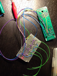
Here are the 4 relais with the step-up converter on the right side on a little extra board:

Endless cabling with the board of the remote:

And finally everything goes into the enclosure. The board with the relais is between microcontroller and rfid reader board. The remote control board I just sticked with double sided tape on the left side to the inside of the enclosure:

They layout how buttons, their LEDs, the 4 relais, the printer and the RFID-reader is connected to the microcontroller looks like this:

The buttons are connected directly. In the firmware we will activate an internal pull-up resistor on the input ports of the microcontroller.
The LEDs are connected directly as well with a 330Ohm resistor, which currentwise is working well. For some reason I've soldered them accidently connected to +5 volts, as I was too lazy to change that later on, I simply inverted the signal in the program. So switching the pin off, when LED should be on and the other way around.
The buttons I've used you can find here: LED Button Adafruit.com I think they are quite cheap for an LED button - and I love their high resolution pictures in the shop. :-)
The relais are connected with a standard transistor layout.
The ATMEGA1284 has two different serial ports, which makes internal programming of the firmware a bit easier. The printer is running at 19200 baud, the RFID reader at 9600.
The layout of the board you can find here: Microcontroller Layout (Pollin.de) on page 7.
I usually buy the whole kit there, (mainly because of the board) and solder only the components I need.
Link to building kit: building kit (Pollin.de)
As microcontroller I've used the ATMEGA1284 instead of the ATMEGA32. This allows me for implementation of a bootloader via ethernet and dhcp support. Which makes firmware updates via tftp server much, much easier during developing.
All firmware files (bootloader and firmware itself) are available here:
Printer Firmware
The bootloader comes with fixed IP and gateway addresses (can be changed of course)
IP 192.168.0.23 and gateway 192.168.0.1 (usually that is the same as router address).
The bootloader expects a tftp server on 192.168.0.40 with the file printerlinkfw.bin
The firmware of the printer can be remote controlled with the following command on linux:
echo "c6 set cmdopt 1" | nc 192.168.x.x 2701 -w 1
This example sets the variable cmdopt to 1 on the microcontroller. It gets send via piping to the nc command followed by the IP address of the device and its port (2701). The option -w 1 allows to see any reply of the microcontroller.
The following values for cmdopt are supported:
1 - switching on LED of green button
2 - switching on LED of red button
3 - switching on LED of white button
4 - switching off LED of green button
5 - switching off LED of red button
6 - switching off LED of white button
8 - switching on remote socket channel 1
9 - switching off remote socket channel 1
10 - switching on remote socket channel 2
11 - switching off remote socket channel 2
If a button gets pressed the printer will send an UDP message like "btn green" to the IP address which is written in the eeprom from address 0-3.
The IP address in eeprom can be programmed with
echo "eew 0 c0a80063" | nc 192.168.x.x 2701 -w 1
for e.g. the IP address 192.168.0.99. (eew starting at eeprom address 0 with the hex format of the IP address)
Reading is the same: echo "eer 0 4" | nc 192.168.x.x 2701 -w 1
(eer start reading at eeprom address 0 and reads 4 addresses)
If an RFID card is read by the reader the printer will accordingly send "rfid" followed by the hex tag of the rfid card.
Sending files to the thermal printer is easy as well. The firmware is listening on port 7970 and sends everything receiving there to the thermal printer:
cat file.txt | nc 192.168.x.x 7970 -w 1
prints out file.txt.
Done :-)

Feel free to comment or ask questions.
:-)
Comments
Post a Comment