It is quite some time ago that I've posted about some of my projects here. On the other hand, there weren't so many recently, except of further completion home automation (like amazon echo integration) and other programming stuff.
For years I have a couple of stepper motors and the necessary electronic components for driving them in one of my workshop shelves. After visiting Las Vegas sometime ago, I thought that a more entertaining project might be to build a slot machine, which is working with real rotating wheels or discs and is controlled by a Raspberry Pi.
Building a port extension for the Raspberry Pi
So before starting with connecting stepper motors with a Raspberry Pi I decided to implement a sufficient port extension right away: controlling the stepper motors, lights and buttons of a slot machine will require a lot of I/O anyway.
To give flexibility how many ports are input and output channels it needs to be a bit more sophisticated than a simple shift register. So my choice is the 8 bit port expander MCP23S08, which is linked via an SPI bus. There is also a 16-bit version of it, but I had the 8-bit version already at home. Plus I never did something with an SPI interface before. :-)
In fact the MCP23S08 can be controlled with 3 connections only: clock, SI (Slave In) and SO (Slave Out). Basically SPI works a little bit like a shift register, but one can send extra bytes e.g. for addressing and setting direction of each I/O pin etc. And it is super fast, which seems to be helpful, when driving stepper motors with it.
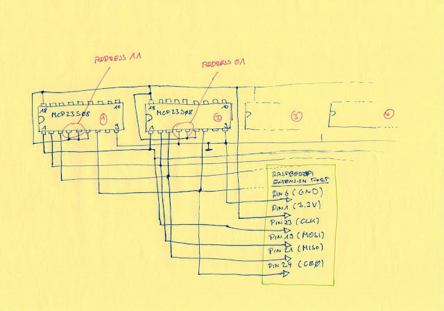
To address the MCP23S08 there are two address pins and one CS (Chip Select) connection. Because I'm using four of these I utilize the address space completely by connecting the address pins of the port expander as 00, 01, 10 and 11. The address is sent in a serial manner via the SI connection of the SPI bus to the expanders. So based on their hardware address it is defined which one is meant by the data sent.
The circuit layout looks like this. To keep it simple I only show two of the in total four expanders:
It looks busy, but is in fact very simple. All 4 expanders are on the same CLK/MISO/MOSI bus. They are also all enabled via the same CS line. So the addressing solely works via the 2 address bits, which are the only two pins which need to be connected differently on each of the four.
I use the 3.3v from the Raspberry Pi to source the expanders with electricity. That way I do not have issues that the voltage levels on the extension port of the Raspberry Pi are rated for 3.3v max.
Connecting and driving a stepper motor
There is a huge amount of documentation out there, how stepper motors are working, what types of motors are available, how to drive them etc. So I will not spend to write a lot about that here, but getting to the circuit layout and how I've implemented it right away.
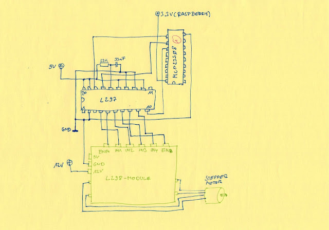
For connecting the stepper I'm using the "classic" combination of an L297 (stepper motor controller) and an L298 (stepper motor driver).
For the latter one I've deployed a ready to use module from Banggood, which is too cheap to solder it myself. (here: Banggood stepper driver module ). Of course this module is a very simple solution: e.g. it comes without current sensing, but so far it is totally sufficient for my application.
Even that I could let the Raspberry Pi control all inputs of the L298 drivers I prefer to make use of the L297: first it is less effort in the software later on, as I don't need to care about the correct pattern of switching on and off the four L298 inputs. Secondly it safes I/O channels.
The MCP23S08 in the layout above is one of those shown in the previous circuit layout. So all the other connections for the MCP23S08 are not shown here. Beside that the L297 is mostly connected like described in its datasheet. The L298 module and the L297 are only sharing ground connection. But the L298 module can also provide 5v with its own regulator, based on the 12V which is used for the stepper drivers in that module. So its 5v connector can be actually an output. But I'm using seperate 5v for the L297. The MCP23S08 is not connected to 5v, as it is also connected to an input of the Raspberry Pi (MISO), hence need to run with 3,3v only.
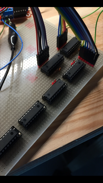
The board with 4 expanders and at that point two L297 looks like this:
On the side of the four MCP23S08 is the cable which is connecting the board with the Raspberry Pi. The two L297 above them are with cabling towards two Banggood L298 modules.
Backside of the board looks a bit busy, but is in the end nothing complicated, as all the expanders are on the same bus connection. So connections are same same for each chip, except the address coding.
On the lower part there is already a third L297 controller soldered, which wasn't on the previous picture.
If everything is connected the right way, a small test program in C drives the stepper motors like this:
The software to control a stepper motor on Raspberry Pi via SPI interface
It is actually not so easy to clock stepper motors directly with linux, as other system tasks can always interfere and causing the motors to stutter or completely stop for a second or two.
Some interesting insights how to handle such problems are discussed here.
For controlling the SPI bus of the Raspberry Pi I'm using the library WiringPi, which can be downloaded here.
But I had to debug it a bit and make two changes in its source code, before the addressing of 4 SPI
based expander worked properly (changed parts a red) :
- In mcp23s08.c, line 175 the init of the MCP23S08
doesn't switch on the device addressing:
So I've changed the constant in IOCON_INIT in mcp23x0817.h, line 82 to
#define IOCON_INIT (IOCON_SEQOP | IOCON_HAEN) - As the MCP23s08 only supports 2 address bits, I had to
change mcp23s08.c line 48 to:
spiData [0] = CMD_WRITE | ((devId & 3) << 1) ;
Probably these changes will be part of future releases of this library - at least I've let the author known that I had to make these changes to get it working...
The complete source code of this small test programm you can find here.
I should mention that this is really only a quick&dirty implementation to see something moving with the two stepper motors and to check on to what extent it is possible to do it on a Raspberry Pi.
In principle it works like this:
- The program consists of three parts:
- a timer, generating a signal every xyz nanoseconds
- a signal handler which is called by that timer and is doing nothing else then posting to a semaphore
- and a seperate thread which is waiting for this semaphore and gives a clock signal to each of the motors and decrease their step counters, then waiting for the next timer signal/semaphore posting. - In main function it gets the three command line arguments necessary to run it properly, which is number of steps the first motor should turn, number of steps the second motor should turn and the speed.
Steps can be also a negative number, in that case the motor turns into the other direction.
Speed is determining the delay for the clock impule times 1000 nano seconds.
In the video you see a speed setting of 1000, which is 1,000,000 nanoseconds = 1ms.
With that setting the programm inverts the clock IO once every 1ms, so a complete period would be 2ms which is a frequency of 500Hz for the stepper motors (=1/0.002).
The smaller the speed number is the faster the stepper motor is rotating. - Then init of the SPI interface is done and the rotation direction of the motors is set based on if number of steps is negative or positive by setting the according output pin high or low.
- Real time priority and memory is locked as recommended in this video.
- After the timer is running, which is then calling the callback function every e.g. 1ms, which in turn is posting the semaphore, where the clock_thread is waiting for, the motors finally getting their clock pulses.
- The main function is then only waiting for a semaphore which is posted by the clock_thread as soon as boths step counters are zero. Then it exits.
One may wonder why not simply a loop with a delay, instead of this more complicated setup with a seperate thread and semaphores?
Well, considering that there will be also other tasks to be taken care of in a slot machine, the program cannot be blocking for only rotating the stepper motors, but still need to know their position at any given point in time. Additionally I want to avoid any "empty" loops which are creating a high processor load on the Raspberry Pi.
The source code is compiled with the command:
gcc engine.c -lpthread -lrt -lwiringPi
The movements of the stepper motors in the video above are done by a simple testing script:
The source code is compiled with the command:
gcc engine.c -lpthread -lrt -lwiringPi
The movements of the stepper motors in the video above are done by a simple testing script:
#!/bin/bash
while true
do
./a.out 400 -1000 1000
sleep 1
./a.out -1000 400 1000
sleep 1
./a.out 200 -200 1000
sleep 1
./a.out 800 400 600
./a.out -400 -800 600
./a.out 400 -1000 600
./a.out -1000 400 600
done
done
Questions or comments? Feel free to comment below.
:-)


Comments
Post a Comment